 | poslední úprava: 17.11.2019 01:13
Portál AbcLinuxu, 1. listopadu 2024 00:37
Recently, someone has suggested on Hacker News to do a basic walk-through capturing some data from radio to a file and demodulating it. So here is my take. I also did this live at InstallFest 2016, but the commentary is unfortunately in Czech. (also, I don't think I'm really into making screencast in English: but maybe I will try some time, sounds like fun :)
I will show this for GNU Radio 3.7.13 (the version now available in most distros); there was a version 3.8 released recently, but I did not have a chance to experiment with it yet.
In Debian, install the gqrx-sdr package, it will pull everything else as dependencies. You will also need some radio hardware, for example a $8 rtl-sdr. If you don't have one, I will provide sample capture file at the end of the post, so you can play with it offline.
So, let's start by running gnuradio-companion. An empty flowgraph will open with two default blocks: Options and a sample_rate Variable. Change the Options to WX GUI, as I think the WX GUI blocks are more user-friendly.
Now we need to add a signal source. Pick an osmocom Source block from the right panel (hint: you can search by pressing /) and drop it to the workspace. osmocom OsmoSDR is a library which has drivers for lots of SDRs and provides a unified API. If you don't see the block, you probably don't have gr-osmosdr package installed.
We need to set the sample rate. For rtl-sdr, set 2.048MHz (you can type for example 2.048e6, but SI multiplies are unfortunately not supported). Leave the frequency at 100MHz (or set some other where there is FM broadcast in the place where you live).
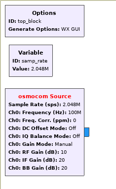
You now have a block that will read data from the radio, but it has an unconnected output - this is illegal, so the name of the block is red. We need to add something to consume the data. Add a WX GUI Waterfall Sink and connect it with the osmocom Source block (by clicking on the first tap and then on the second).
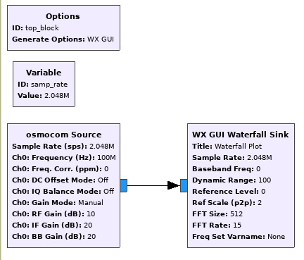
Now click the Run button. You will be prompted to save the result and then it will be "compiled" (into an intermediate Python code) and executed.
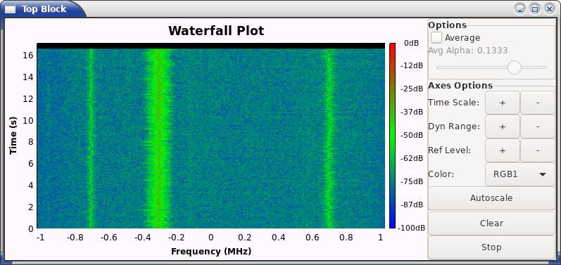
This display is usually called "waterfall". The Y axis shows time, the X axis shows frequency, and color shows the power detected at the given [time,frequency] point. And we see a chunk of spectrum centered at our receiver's frequency and spawning from -sample_rate/2 to +sample_rate/2. Notice that we are working with a complex-sampled signal, so we have negative and positive frequencies - contrary to real signals (which are common for example in audio processing), the complex wave can rotate clockwise or counter-clockwise in the complex plane, hence the positive or negative frequency. Unfortunately further explanation of this phenomenon is out of scope of this tutorial; you can try this guide, this illustrated guide or the first chapter of my master thesis.
As the center frequency of our receiver is 100MHz, we can see that there is some strong signal at 99.7MHz (100-0.3) and two weaker signals at 99.3MHz and 100.7MHz.
This is a common situation: we have multiple transmitters in our capture and we need to separate them. This is also advantageous: you can receive multiple things at once with one SDR! Now let's concentrate on that signal at 100.7 MHz.
First, we will use a block called Frequency Xlating FIR Filter. This block can "shift", or "translate", the frequency of a signal. So for example we have that weak signal at +0.7MHz, and we need to shift it to 0, because one usually wants to work with signals that are zero-frequency-centered. Internally, the block does this by generating a new signal with frequency -0.7MHz and multiplying the two signals together.
So remove the connection between the blocks and insert an Xlating block in between. Set the Center Frequency to 700kHz. There is also a mandatory field called "Taps"; for now, just put [1] (a Python list containing a number 1) there, I will explain this later. Click Run again.
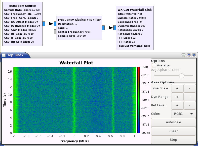
We can see the waterfall looks similar to the previous one, but the image is shifted and wrapped around. And our target signal is now at the frequency 0. However, there is still a lot of other stuff, so we need to pick up our target signal and remove everything else.
We will use a low-pass FIR filter to attenuate everything beyond certain frequency, say +/-70kHz (we can estimate - or look up - that the signal is about 140kHz wide).
To generate a FIR filter, we can use lots of on-line tools or the builtin generator in GNU Radio. Start a Python (2.7) interpreter and enter:
>>> from gnuradio.filter import firdes
>>> firdes.low_pass(1, 2048000, 70000, 20000, firdes.WIN_HAMMING)
(0.00019855154096148908, 0.00018326807185076177, 0.00015975582937244326, ...)
The first parameter is the filter gain, leave it to 1. The second parameter is the sample rate - 2.048MHz for our radio. The third parameter is the cutoff frequency - 70kHz for our signal. The fourth parameter is a transition band: it is not possible to create an ideal filter that passes everything from 0 to 70kHz and attenuates everything else, so we say with this "between 60 and 80 kHz is a transitional area". The fifth parameter is the window used to create the filter, which for now does not really matter.
We can plot the frequency response of the resulting filter:
from gnuradio.filter import firdes
b = firdes.low_pass(1, 2048000, 70000, 20000, firdes.WIN_HAMMING)
from scipy import signal
w, h = signal.freqz(b)
import matplotlib.pyplot as plt
import numpy as np
plt.plot(w, 20 * np.log10(abs(h)), 'b')
plt.ylabel('Amplitude [dB]', color='b')
plt.xlabel('Frequency [rad/sample]')
plt.show()
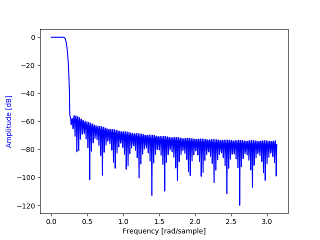
Now, we need to filter the signal with the resulting coefficients. You can either copy-paste them to the Taps field of the Xlating block, or you can just enter firdes.low_pass(1, 2048000, 70000, 20000, firdes.WIN_HAMMING) there - the fields can contain Python code that will be evaluated.
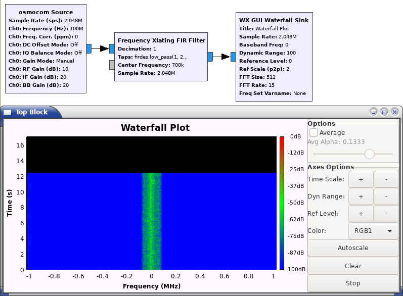
Now everything else disappeared and only our target signal is left. However, you can see there is a lot of empty space: the signal is still sampled at 2.048MHz, despite the effective bandwidth being only 140kHz. We need to decimate it.
Decimation is a process where we drop some samples from the signal. For example, in our case, we will drop 7 samples out of every 8, decreasing the sampling frequency to 2048/8 = 256kHz.
The Xlating block has a convenient option for this: Decimation. Set it to 8.
However, if you now run our flowgraph, the waterfall display will be very slow and the frequencies will be all wrong: it still expects data at the original sample rate! So also edit the Sample Rate parameter of the Waterfall Sink to samp_rate/8.
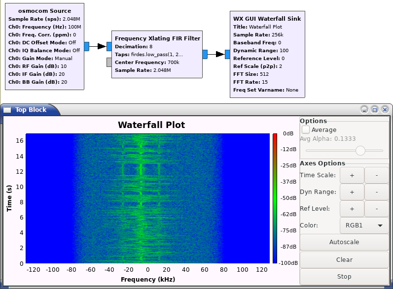
Now our signal is in a reasonable form. We can even see the modulation and guess that it's FM broadcast of speech with pauses between words. We can also see that the center of the signal is pretty off as rtl-sdr uses crappy clock and I have not calibrated it beforehand.
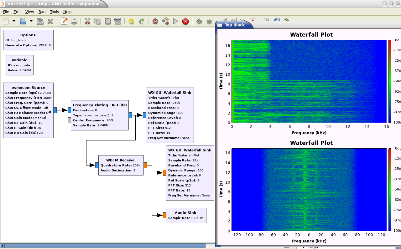
Now the last step: demodulate the audio. We will use a WBFM Receive block. Set Quadrature Rate to the sample rate of the (filtered and decimated) signal, that is, 256e3, and Audio Decimation to 8: it will take 8 samples from the input and output 1 sample of audio; that is, the audio will be sampled at 32kHz, which is a sample rate supported by most sound cards.
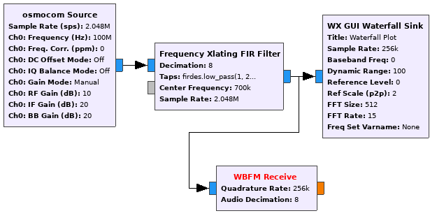
Notice the output tap of the receiver is orange: that's because it is real. You can get information about colors, which GNU Radio Companion uses to distinguish data types, in Help→Types.
Now add another Waterfall (don't forget to switch it to real and set the sample rate correctly) and an Audio Sink. And ta-daaa: you should see spectrogram of the sound and hear it!
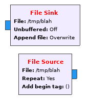
There are blocks called File Sink and File Source. You can simply connect them anywhere in your flowgraph and File Sink will dump what you send to it to a file. File Source will load data from a file and dump them to your flowgraph. The format of the file is just a stream of complex floats, that is, each sample is one 32-bit float (in your machine endianness) for the real part and one for the imaginary part.
This is however a bit wasteful, especially if you are recording the entire baseband: your SDR has probably only 8bit (rtl-sdr) or 12bit (higher-end devices) AD converter, and we are using 32 bits for each sample. So if I need some longer recording and need to conserve space, I use the program from the SDR vendor (rtl_sdr CLI tool for rtl-sdr) which can give you the raw samples. You must then convert it to floats with appropriate blocks in GNU Radio. For example, I have captured a file with rtl_sdr:
$ rtl_sdr -f 100e6 -g 20 -n 10000000 fm.binand the GNU Radio flowgraph looks like this:

We convert the uint8_t samples to float, remove the DC offset (the output is uint8_t where zero is 127.5 and the signal goes up and down), normalize it from -127..127 to -1..1 and merge two consecutive samples into one complex sample. Yes, it's a hassle, but the file is 4 times smaller.
You can download the file here.
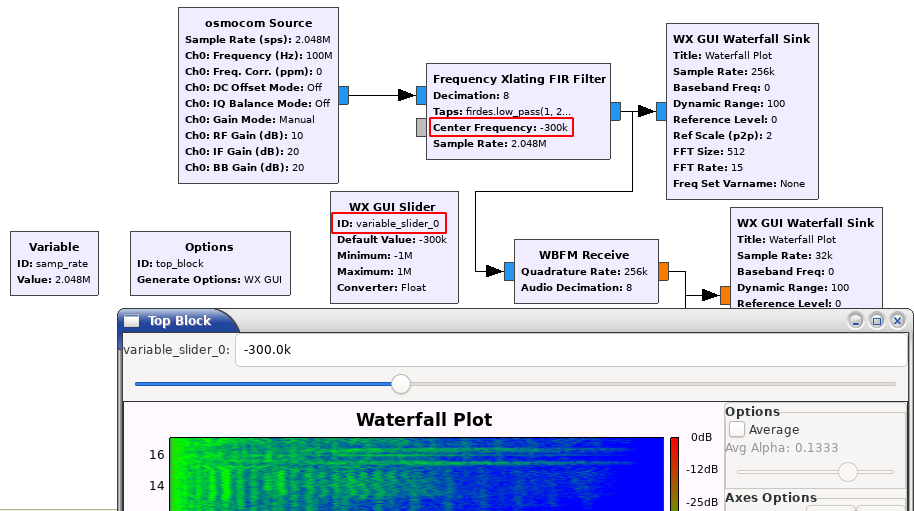
You can add GUI blocks, for example WX GUI Slider, that allow you to control parameters while the flowgraph is running.
Add a GUI Slider, set a reasonable range (for example -1 to +1 MHz) and copy its ID (default: variable_slider_0) into the control you want to adjust: for example into the Center Frequency parameter of the Xlating block. Now when you run the flowgraph, you can tune your radio.
You can see in the console (or in process manager of your operating system) that every time you click Run, it generates a Python script and runs it. The code looks something like this (truncated for brevity):
#!/usr/bin/env python2
from gnuradio import *
class top_block(grc_wxgui.top_block_gui):
    def __init__(self):
        self.wxgui_waterfallsink2_1 = waterfallsink2.waterfall_sink_f()
        self.Add(self.wxgui_waterfallsink2_1.win)
        self.osmosdr_source_0 = osmosdr.source( args="numchan=" + str(1) + " " + '' )
        self.osmosdr_source_0.set_sample_rate(samp_rate)
        self.osmosdr_source_0.set_center_freq(100e6, 0)
        self.freq_xlating_fir_filter_xxx_0 = filter.freq_xlating_fir_filter_ccc(8, (firdes.low_pass(1, 2048000, 70000, 20000, firdes.WIN_HAMMING)), 700e3, samp_rate)
        self.audio_sink_0 = audio.sink(32000, '', True)
        self.analog_wfm_rcv_0 = analog.wfm_rcv(quad_rate=256e3,audio_decimation=8)

        self.connect((self.analog_wfm_rcv_0, 0), (self.audio_sink_0, 0))
        self.connect((self.analog_wfm_rcv_0, 0), (self.wxgui_waterfallsink2_1, 0))

if __name__ == '__main__':
    tb.Start(True)
It instantiates the blocks, connects them and runs them. You can use this top_block object in your own code and do whatever you want: you have a radio receiver controlled from your own Python program.
Tiskni
Sdílej:
![]()
![]()
![]()
![]()
![]()
![]()
tam piše v odstavci installation že ti stačí obyč rtl-sdr za vosum doláčů a takovejch je plná čína ;D jde tam najít i novej nepoužitej levnější mam otamtaď za ~5$ ale už se mi nedařej najít takže ty žlutý děti co je montovali se asi už zadávili neschválenejma chemickejma stabilizátorama z čínskejch jedovatejch plastů :D doporučuju z těch rtl-sdr svlíkat plastový pouzdra a ekologicky je spálit za vysoký teploty v kamnech. jako bonus se budou odhalený součástky líp chladit jen si pak musíš dávat pozor u zajímavejch signálů abys třeba ty čipy neposlintal když už teda nejsou chráněný ;D
a bude se taky chytat družice na kus drátu?? je to celkem snadný a zajímavý ;D
supr pohlednice z nízký orbity náhodou :D horší by bylo kdybys na ně do někde do tří do čtyř ráno čekal než poletěj v rozumný elevaci a voni zrovna chrápali a neposílali dolu nic ;D
a podařilo se ti chytit LRPT novýhoj ruskýho meteoru M 2-2 taky někde na těch dvou metrech?? na githubu je někde skript na chytání toho starýho ale ten už s novým satelitem nefunguje a je v tom asi něco víc než že se jenom přepne ten symbol rate ze 72k na 80k :'(
a podařilo se ti chytit LRPT novýhoj ruskýho meteoru M 2-2 taky někde na těch dvou metrech??Nezkoušel jsem.
kdyby ses třeba jednou strašně nudil tak hele ;D
To je první krok k čemukoli, co chceš s digitálním signálem dělat.= nic
vypadá jak autorádio simtě :D :D :D :D
to je jako na co přesně tam ten integrovanej elektronickej klíček??
jsem nečekala že to radioamatéři ještě dneska řešej tak staromódně teda :D ale asi by byla menší sranda strčit do vysílače z kompu usbčko a nechat komp za sebe všechno udělat. nevim.
ale asi by byla menší sranda strčit do vysílače z kompu usbčko a nechat komp za sebe všechno udělat.Přesně tak, radioamatéřina je pro zábavu (a poučení) a to platí i pro CW. Možná se to nezdá, ale morseovka je pro lidi, pro stroje až tak moc ne... Komp samozřejmě můžeš nechat všechno dělat, říká se tomu digi módy
 Na přenášení textu jsou určené RTTY, PSK a další...

<lama>Na to nepotřebuje skutečné SDR, ale stačí přepnout přijímač do SSB módu, zdemodulovaný signál dát do zvukovky/navzorkovat na 8 kHz, a úzký filtr udělat na tom, ne?</lama> (někdo by mohl říct, že tím se vlastně udělalo skoro-SDR, což je pravda, ale spustí to na tom FTčku nebo libovolně historickém SSB přijímači)
 .
.
ISSN 1214-1267, (c) 1999-2007 Stickfish s.r.o.